SCR-270
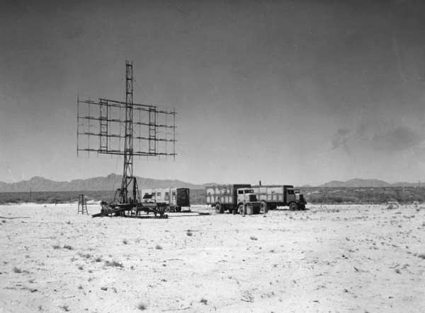
Photo courtesy of the White Sands Missile Range.
This radar was at White Sands Proving Ground sometime in the mid 1945 to mid 1947 time frame - maybe longer.
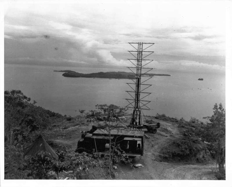
This is reported to be the actual Pearl Harbor SCR-270 radar at its site in Hawaii.
Contributed by Jim Hewett
|
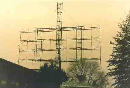
This photo shows a
restored model of the "Pearl Harbor radar," type SCR-270. The photo was taken in front of the Historical Electronics
Museum near BWI Airport, Baltimore, MD.
|
|
From the collection of Wray B.K. Taylor, II
SCR-270 HISTORICAL NOTES
by Don Helgeson,
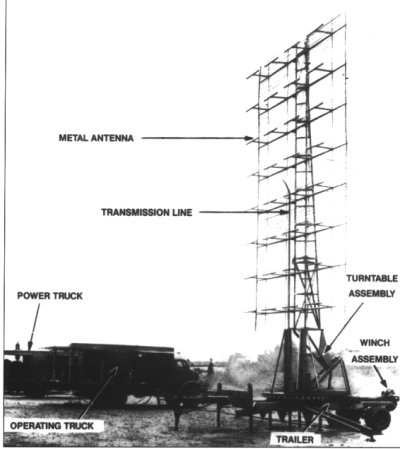
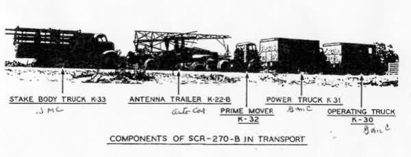
A mobile SCR-270 radar set. On December 7, 1941, one of these sets detected Japanese aircraft approaching Pearl Harbor. Unfortunately, the detection was misinterpreted and ignored. Photo from "Searching The Skies" |
The U. S. Army Signal Corps "Set Complete Radio, NO. 270", or SCR-270, deserves yet another footnote in the various bio/histories of "Hap" Arnold. I think that he started the U.S. Army Air Corps, radar program.
When one reads the May 5, 1937 letter, written by "Lt. Col. M. F. Davis, Air Corps," down in the Panama Canal Zone, to the Chief Signal Officer (CsigO), requesting "radio equipment... which might be used to detect the presence of aircraft by reflected signals..." One wonders what would motivate a Lt. Col., assigned to a remote fighter squadron, to bypass normal command channels by sending a request directly to the Chief Signal Officer in Washington. We can only assume that Air Corps Headquarters Staff was in on this idea........ Can you sense the master mentor Arnold, at work? "Buck (The Signal Corps) a request for some sort of a radio detection device for spotting aircraft... Lord knows they are up to something at Fort Monmouth and if they don`t have the answer, the Navy must have it.... Lets face it, the fellows at the Naval Radio Labs have been lobbing congress for years, for radio detection money". (N #1)
As it happened, the SCL was ready to show off their new combination infra-red/radio detection system, so the Chief Signal Officer sent (his first) endorsement of the Davis letter, along to the Chief of the Air Corps. (Note the more correct form of communication here one Corps Commander to another..) The Assistant Chief of the Air Corps, Brigadier General H. H. Arnold was invited up to Fort Monmouth on the 18th of May. Following this successful demonstration, Arnold`s boss; Major General Oscar Westover and a host of dignitaries from the War Department and Congress attended another demo on the 26th.
On 5 June 1937, "Hap" Arnold had sent a second endorsement to Davis`s letter to the CSigO: (the Air Corps is) "firmly convinced that apparatus required for use in connection with the problem presented in the basic communication can be developed by application of the basic principled employed in the equipment demonstrated"...... Work on Air Corps radar had begun. In the summer of 1937, negotiations were entered into, with RCA and Westinghouse for Research and Development of ten high power Very High Frequency triode tubes.
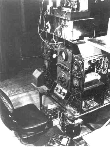
The SCR-270 operating position shows the antenna positioning controls, oscilloscope, and receiver. Photo from "Searching The Skies" |
One must understand that radar transmitting tubes were analogous to aircraft or rocket engines, in those days. Just as a fighter aircraft tended to be designed around the latest engine, radio and later radar transmitters were designed around the most efficient vacuum tube that was otherwise qualified. In the case of early radar equipment, high power at ever increasing frequencies was the quest of the tube designer. Poor tube = bad set.
Westinghouse won the bid at $12.5k and put Ilia Emmanuel Mouromtseff to work, up in Bloomfield, New Jersey, on the water cooled tube that would power the SCR-270. Given the development numbers 3007 & WX3007, the final version was assigned the Westinghouse catalog number WL-530. (The WL- numbers were assigned in random order) In due time, the Signal Corps Vacuum Tube number VT-122 was assigned to the WL-530. The money purloined from the Coast Artillery`s radar project. This turned out to be a very timely move, since state of the art hardware was involved and we all know how long that sort of thing takes.
We can now move on to the story of how the SCR-270 evolved from the SCR-268 prototype, quite literally on the sand dunes of Sandy Hook.
The U. S. Army`s various histories are very candid about the fact that the SCR-270 was built at the expense of the Army`s Coast Artillery Corps SCR-268 searchlight control radar. In fact, the first version of the prototype SCR-270 used a transmitter borrowed the SCR-268, slowing down the latter’s development program.
Bob Dwight, of the Historical Electronic Museum, near Baltimore, Maryland, was able to lighten up a murky area in the histories. It seems that the SCL ordered key SCR-270/1 model and prototype components from Westinghouse Electric, in January of 1940. This information, tidies up many loose ends. That is the reason why the equipment of the original Panama Canal SCR-271 installations, in late 1940, bore Westinghouse nameplates.
The early SCR-270/1 components were the BC-405 Transmitter, built around the VT-122/ WL-530 tube, its modulator called the BC-402 Keyer, and the RU-3 water cooler. A Westinghouse generator driven by a Le Roi gasoline engine was given the designation (Power Equipment) PE-74.
RCA built the BC-403(*) 5" oscilloscopes and the BC-404(*) receivers as a subcontractor. The first of the BC-404`s used a state of the RCA art, "Orbital Beam tube," VT-123, that evolved into the 1630/ VT-128. (2nd RF Amp. )
The RA-33 15 kV, high voltage power supply common to both the prototype SCR-268 & `270/1, was built by another contractor, L.H. Terpening, whose shop produced several early Army radar components. (Later replaced by the Westinghouse RA-39, in the SCR-270-B and the similar RA-60 in later `270/1 models. These later rectifiers used the unique WL-531/ VT-141 rectifier tubes.)
The Couse Company, of Newark, New Jersey, a supplier of well drilling rigs, designed and manufactured the K-22/SCR-270(*) antenna mount trailer as well as its successor the K-64/SCR-270(*).
A look at the mid nineteen-thirties might be useful to put things in perspective. "The war to end all wars" had been over for nearly two decades, the great depression of the thirties had followed the stock market crash of 1929 and money was tight. With the inevitable shortage of tax dollars, many Government workers at every level were laid off.
Moreover, the stage was being set for World War Two. Japan had invaded mainland China and occasionally fighting Russia. Hitler was helping the fascists win the war in Spain, while his "ally" Stalin, was doing likewise for the Republican opposition. Business as usual.
The Douglas DC-3 and the Boeing B-17 Flying Fortress were flying at speeds that exceeded some of the fighter aircraft on hand and this tended to render acoustic detection of aircraft less than useful. Although in common use at this time, as witnessed by the adoption of the 1936 model sound detector, one must consider the decrease in usefulness of sound detection in an inverse relationship with the ever increasing speed of aircraft, due to the relatively slow speed of sound waves in the atmosphere. (700 odd MPH.). The main use of sound locators in World War Two seemed to be misinformation.
Pictures and descriptions of sound locators as used in the military maneuvers of 1940 and 1941 were trotted out time and again, to "explain" the detection of aircraft.
Some of those who tuned some of the old homemade radio sets with a long stick to prevent body capacitance from affecting the sets tuning must have wondered is this troublesome effect could be put to some good use. Reflection of Hertzian or radio waves had been in the literature for over fifty years at this point in time so the idea was not unique.
Tesla predicted radar in 1900, Hulsmeyer patented a non-ranging but working 600 MHz spark gap detector in 1904 and Marconi`s remarks in 1922 helped point the way.
The Signal Corps Laboratories [SCL], at Fort Monmouth, New Jersey developed tactical telephone switchboards BD-71 & 72, that were designed around surplus WW-I drop coils. The long lived BC-191/375 high frequency radio transmitter, that used VT-4-C tubes, a variant of a tube conceived during WW-I. was abstracted from a Collins Radio design (N # 3). Its companion radio receiver was the BC-184.
Radio equipment for use in light aircraft, such as the SCR-183 was basically comprised of the BC-183 transmitter and BC-230 receiver and its accessories, that were merely relabeled equipment, of U.S. Navy design.
On the other hand, the ubiquitous EE-8 field telephone was being put into limited production and work had started on a whole new endeavor, "Radio Position Finding" or "R.P.F.", later (By late 1941) called radar. (N# 4)
Major (later Colonel) W.R. Blair, the Director of the Signal Corps Laboratories at Fort Monmouth, New Jersey, (SCL) had decided to pursue the subject of aircraft detection with the short Hertzian waves, now termed microwaves, that he studied at the University of Chicago. (N #2)
The Corps of Engineers and the Ordnance Corps were working on infrared aircraft detection, a subject of 1918 research by Master Signal Electrician S.A. Hoffman, at Columbia University but Blair was able to get the infrared research transferred to the Signal Corps Laboratories, by February of 1931.
"Project 88: Position Finding by means of Light" became the springboard for the U.S. Army`s radar research. Blair`s 1906 doctoral thesis gives us a hint of the direction he was to pursue at Fort Monmouth. A student of Miliken at Chicago University, his thesis included research into the phenomenon of the reflection of Hertz waves at ultra high frequencies. Therefore, it comes as no surprise that Blair had decided to pursue the use of radio waves to illuminate aircraft, as a means to detect the presence of aircraft aloft. In order to justify this radical change in the direction of his assigned research, he engaged the services of the leading experts in the field of photometry. This approach, led to the development of a viable infrared detector and produced formidable advances in that art.
"RAY WHICH DETECTS SHIPS OFF SHORE TO BE TESTED AT HIGHLANDS" (New Jersey) and "MYSTERY RAY SEES `ENEMY` AT 50 MILES": were two of the area newspaper headlines resulting from a test of the Signals Corps infrared tracking equipment. U.S. Coast Guard Rules required a formal "Notice to Mariners" to posted "Conspicuously" in July of 1935, due to the use of a searchlight in conjunction with night tests of the infrared tracker.
An information request from: "Okra & Company", a Japanese firm, was turned down flat, by SCL Lt. Col. (later Major General) Colton, who succeeded Blair as director of the Signal Corps Labs.
The Signal Corps was able to buy a few of Kilgore`s magnetron`s of the same type displayed, in the Westinghouse display at the "Century of Progress Exposition," the Chicago Worlds Fair of 1933. Work proceeded on both infrared and radio detection methods. Due to the low power output obtainable from the available microwave devices, in 1934 through late 1940, the infrared detection equipment functioned at much greater range than the Signal Corps early Continuous Wave (CW) microwave radio detection equipment.
In the meantime, the U.S. Navy Radio Labs had decided to try radio detection at much lower Radio Frequencies (RF), where much more transmitter power could be generated. The Navy had been involved in research of this sort from 1922 on. The idea of using short radio waves for secure communication between nearby ships had been demonstrated and served as an excuse for the NRL to pursue Very High Frequency (VHF) radio detection research. As a case in fact, the first Navy radar receiver had an audio output stage and a headphone jack, in addition to the video output, to disguise its true purpose, for the budget.
The reason that first Navy pulse radar operated at the relatively low frequency of 28.3 MHz, was the availability of existing antennas, previously constructed for communication research.
The use of short bursts or pulses of transmitted radio energy was found to be helpful and this led, in turn, to the second big Navy radar breakthrough, Leo Young`s radar duplexer. NRL’s use of EIMAC 100TH tubes, in a ring oscillator, at 200 MHz, was an important step also.
Up until the U.S. Navy`s invention of the radar duplexer, separate antennas for transmitting and receiving, had to be employed, a cumbersome impediment. The innovative, integrated, 200 MHz radar set called the XAF, was completed late in 1938 and successfully demonstrated on the Battleship USS New York during the Caribbean naval maneuvers of 1939. (N #5)
The development of the above equipment was shared with the SCL as early as 1936, by order of the war department. W. D. Hershberger, of SCL, visited NRL and was influential in implementing the pulse technique at Fort Monmouth.
[Historical Electronic museum, Phone; 410-765-2345, -New Address: PO Box 746, Mail Stop 4015, Baltimore, MD 21203.]
NOTE #1:
The U.S. Army Signal Corps adopted the SCR- designations during WW-I. The term SCR- was generally accepted as "Signal Corps Radio" by WW-II. One must note, however, that the term can also apply to such things as The SCR-169 storage battery charging set, as described in my copy of TM 11-302, December 10, `41. { NOTE #1 contd.; The entire text of Lt. Col.. Advisee’s April 1937 letter to the CSigOfc.. ? With endorsements ?}
NOTE #2:
"Change of phase due to the passage of electric waves through thin plates...", Physical Review, Vol. 26, NO. 1, January 1906.
NOTE #3:
Western Electric type 211 tubes were not produced until 1921. The later VT-4C`s were used in WW-II BC-191 for @12 volt operation and the BC-375 @24 volts. The writer, then in the 206AAA Group, California National Guard, was issued an SCR- set that contained a BC-191 in 1957 ! The mere existence of the unstable, obsolete, BC-191 transmitter in 1957, even in a reserve unit, is mute but unshakable testimony to the fact that an important portion of 1930`s Signal Corps meager communication research budget and man power was diverted to radar research. Also check Alan Douglas` article in the Antique Wireless Assn., Old Timers Bulletin `91.
NOTE #4:
The U.S. Navy adopted Capt. S. M. Tuckers 1940 acronym: "RADAR", derived from: RAdio Direction And Ranging, on the recommendation of Capt. F. R. Furth.
See: Chief of Naval Operations Document 31767, 9 July 1941 and the U.S. NAVAL INSTITUTE PROCEEDINGS No.775, Vol. 93, No. 9, September 1967.
NOTE #5:
Another radar, a 400 MHz set, made by RCA was installed on the U.S.S. Texas, it was a failure.
British R.D.F {radar} duplexer development does not seem to have made much progress, prior to the mid 1940, Tizard mission visit to the U.S., with the priceless gift of the microwave magnetron. General Electric built the SCR-527, a was (U.S.)copy of the British CHL/GCI. The SCR-527 was an excellent example of a typical British VHF radar, of the type, that had separate antenna`s for transmitting and receiving, due to the lack of a duplexer. I firmly believe that the U.S. taught the British how to make radar duplexer`s.
In order to equip the SCR-270 with a PPI, for example, the BC-1239-A Receiver- Indicator console, was borrowed from the SCR-527. (This subject requires a whole chapter!)
Don Helgeson,
Tel. 1-847-676-4604/29.


