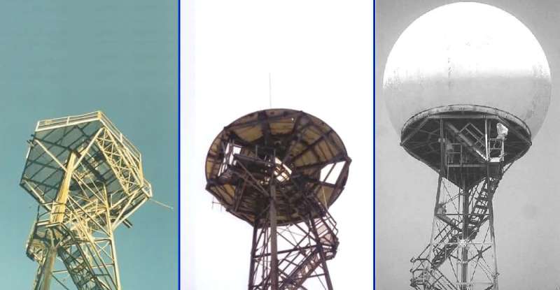
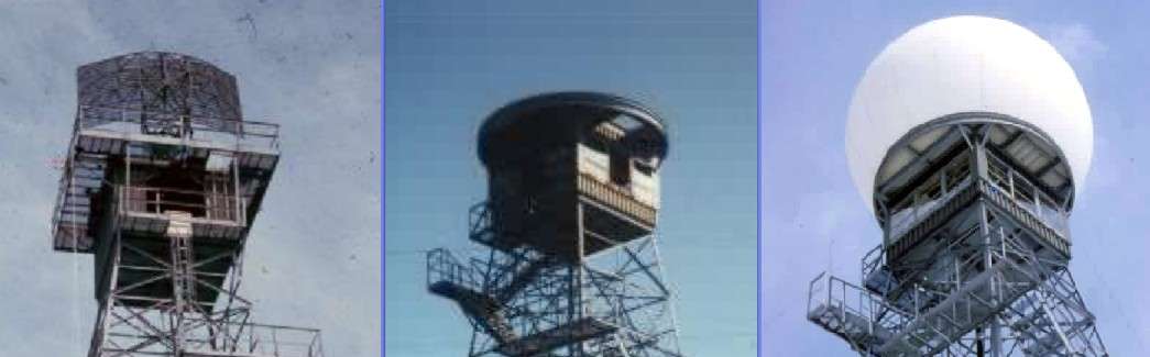
As shown in the two figures (below), adding a radome to an existing AN/FPS-14 or AN/FPS-18 gap-filler radar tower was a multi-step process. And, there were slight differences if the radar tower was the standard three-legged version or the less-typical four-legged version (which doubled as a fire-lookout tower in three of the four known instances). For both types of towers, the antenna-deck railings first had to be removed. For the three-legged tower version, a circular adapter was then added to the hexagonal antenna deck. For the four-legged tower version, most of the overhanging parts of the square antenna deck had to be removed; then a circular adapter was added to the remaining antenna deck, with support braces also being added from the adapter to the tower cab at its corners. For both tower types, the radome was next set in place (in sections) and secured. Finally, the radome`s seams were caulked, and the whole dome was painted white. A red aircraft-warning light was also affixed to the top of the radome. Radomes were first fielded at certain gap-filler annexes, mainly at northern locations, beginning in 1963. [Note that -- for illustrative purposes only here -- certain `recent` pictures of radar towers were used, and their radar antenna assemblies had long since been removed. In actuality, the radar antenna assemblies were left in place on the towers while the radomes were being installed.]